If you follow electric vehicles, AI data centers, solar inverters, or high-efficiency switching power supplies, you have already seen the same engineering pressure: higher power density creates stronger electromagnetic interference. EMI is the unwanted electrical noise that can disturb control boards, communication lines, sensors, and neighboring power circuits.
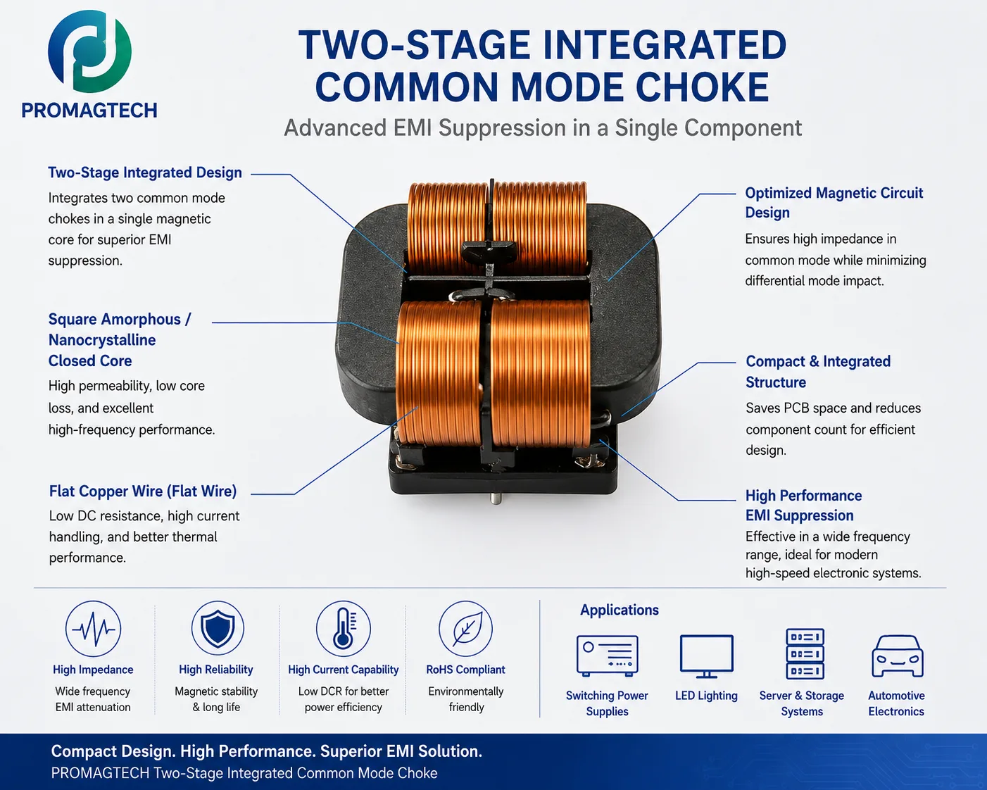
The two-stage integrated common mode choke is designed to suppress that noise while saving PCB space. Instead of placing two separate common mode chokes in series, the design integrates two filtering stages into one magnetic structure.
Where It Is Used
OBC power stages need EMI filtering that can handle high current, limited space, high temperature, and automotive reliability requirements.
High-efficiency server power architectures require compact EMI filters that fit dense chassis layouts without disturbing adjacent circuits.
High-frequency conversion creates conducted noise that must be controlled before it travels through the system or grid-side interface.
Why Two Winding Gauges Are Used
On many two-stage integrated common mode chokes, the two copper windings are not identical. This is not a random cost choice. It is a way to target different frequency ranges and current stresses inside one component.
The thicker winding: low-frequency noise and current handling
Low-frequency common mode noise can require higher impedance and stronger current capability. The thicker flat copper winding helps reduce DC resistance and temperature rise while carrying the main power current safely. For high-current EV charger or inverter designs, this part of the structure protects thermal margin.
The thinner winding: high-frequency noise and parasitic control
High-frequency noise behaves differently. If the winding is too large or too close, parasitic capacitance can allow noise to bypass the filter path. A thinner winding can reduce inter-winding capacitance and improve high-frequency attenuation. Because high-frequency current tends to concentrate near the conductor surface, conductor geometry matters more than copper volume alone.
Core and Winding Structure
- Two-stage integrated design: combines two common mode filtering sections in one magnetic component to reduce component count and PCB area.
- Square amorphous or nanocrystalline closed core: provides high permeability, low core loss, and useful wideband EMI suppression characteristics.
- Flat copper wire: supports lower DCR, better current handling, repeatable winding shape, and improved thermal contact when the process is controlled.
- Optimized magnetic circuit: raises common mode impedance while limiting unwanted differential mode impact.
Manufacturing Difficulty
Integrating two asymmetric winding gauges onto one magnetic core is more difficult than winding a simple common mode choke. The process must control winding tension, spacing, insulation, soldering, magnetic coupling, and repeatability. For export projects, the buyer should ask for the actual impedance curve, DCR, temperature rise, insulation test, and reliability test scope instead of judging the part from appearance alone.
What To Send For Review
For a two-stage integrated common mode choke review, send the converter topology, rated voltage, rated current, switching frequency, target EMI standard, impedance requirement, DCR limit, insulation requirement, PCB space, cooling condition, and expected annual volume.
Download the PDF Data Guide
Download this ProMagTech engineering resource as a PDF for internal design review and supplier discussion.
Download PDF DataRelated Engineering Resources
High-frequency amorphous CM inductor
Amorphous-core EMI filter magnetics for SiC/GaN and compact power modules.
Three-phase common mode inductor
Three-phase common mode chokes for inverter and storage converter EMI filtering.
Common mode inductor EMI design guide
Core material, winding and impedance review points for conducted EMI suppression.
Frequently Asked Questions
What is the main engineering decision in Two-Stage Integrated Common Mode Choke for Advanced EMI Suppression?
The main decision is to match electrical stress, frequency, thermal path and mechanical envelope before confirming the magnetic component structure.
Which parameters should be provided for a custom review?
Provide input and output voltage, switching frequency, current waveform, target inductance or turns ratio, temperature limit, insulation requirement and mechanical drawing.
Can the values in this guide be used directly in production?
No. The values are design references. Production values should be confirmed through approved samples, DC bias checks, DCR measurement, hi-pot test and thermal validation.