
Project Background
The design target was a compact high-current inductor for a bidirectional DC-DC converter stage. The engineering question was not only the nominal inductance value, but whether the selected core, turns count, winding cross-section, DCR target, insulation structure and mechanical envelope could remain credible under 40A operating current and 60A saturation-current review.
Design Requirements
66kHz Design Snapshot
| Parameter | Public-safe engineering value |
|---|---|
| Switching frequency | 66 kHz |
| Input voltage range | 740-860 VDC |
| Output voltage and current | 120 VDC / 40 A |
| Target inductance under rated current | 100 μH class at 40 A |
| No-load inductance reference | About 195 μH class in the sample-stage specification |
| High-current inductance checkpoint | At 60 A: 70 μH class target in the sample-stage specification |
| DCR | <10 mΩ target / 10 mΩ max class at 25°C |
| Turns reference | 38 turns class |
| Core reference | EQ32 Fe-Si magnetic core, μe 60 class |
| Use of published data | These values are anonymized design evidence. Final production values must be tied to the approved drawing, sample record and test report. |
Mechanical Envelope Evidence
The mechanical review focused on whether a flat-wire winding and rigid terminal structure could fit inside a compact 35 mm diameter-class and 40 mm height-class package while keeping terminal spacing, lead protection and assembly repeatability under control.

High-current inductor product views
Product-view evidence showing top, side and bottom pin-layout views for the high-current flat-wire inductor case, including the compact package, copper winding window and terminal layout.
DC Bias and Saturation Review
For high-current inductors, the risk is that the no-load inductance looks acceptable while the inductance collapses under DC bias. The Fe-Si 60u review showed the expected permeability roll-off as DC magnetizing force increases. That makes the 40A and 60A checkpoints more important than nominal inductance alone.
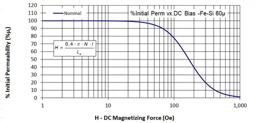
The curve is used here to explain engineering method, not as a universal guarantee for every custom design. Core geometry, turns, air gap, winding structure and thermal conditions must be checked per project.
Material and Construction Evidence
Quality Assurance Scope
The sample-stage quality scope included inductance checks, DCR checks, appearance inspection, and insulation-related review. For the 66kHz option, the public-safe specification reference included 1.5 kVAC / 60s dielectric strength between winding and core and insulation resistance at the 100 MΩ class. These values should not be reused for another project without confirming the approved requirement.
What This Case Proves, and What It Does Not Prove
This case proves that ProMagTech can convert a high-current converter requirement into a structured magnetic design review: frequency option, no-load and loaded inductance, DC bias roll-off, DCR target, thermal class, insulation stack and compact terminal geometry. It does not prove mass-production approval, buyer endorsement, universal temperature-rise performance or certification status.
What Engineers Should Send for Custom Review
Send the converter topology, input and output voltage range, output current, switching frequency, ripple target, rated-current inductance, saturation-current requirement, maximum DCR, mechanical envelope, insulation requirement, cooling condition, terminal preference and expected validation items. For high-current flat-wire inductors, the 40A and 60A operating checkpoints are more useful than nominal inductance alone.
Download the PDF Guide
Save this 120V 40A 66kHz flat-wire inductor design case as a PDF reference for internal design review or supplier discussion.
Download PDFRelated Engineering Resources
High current flat wire inductor
Custom high-current flat wire inductors for EV, storage and industrial converters.
Flat wire inductor selection guide
Compare flat wire and round wire winding for DCR, thermal path, saturation behavior and power density.
High power density flat wire magnetics white paper
Round-wire versus flat-wire trade-offs for window fill, AC loss, thermal path and production consistency.
Frequently Asked Questions
What is the main engineering decision in 120V / 40A / 66kHz High-Current Flat-Wire Inductor Design Case?
The main decision is to match electrical stress, frequency, thermal path and mechanical envelope before confirming the magnetic component structure.
Which parameters should be provided for a custom review?
Provide input and output voltage, switching frequency, current waveform, target inductance or turns ratio, temperature limit, insulation requirement and mechanical drawing.
Can the values in this guide be used directly in production?
No. The values are design references. Production values should be confirmed through approved samples, DC bias checks, DCR measurement, hi-pot test and thermal validation.